Unique Info About How To Draw A Smith Chart
Smith Charts
What Is Smith Chart And How To Use It For Impedance Matching
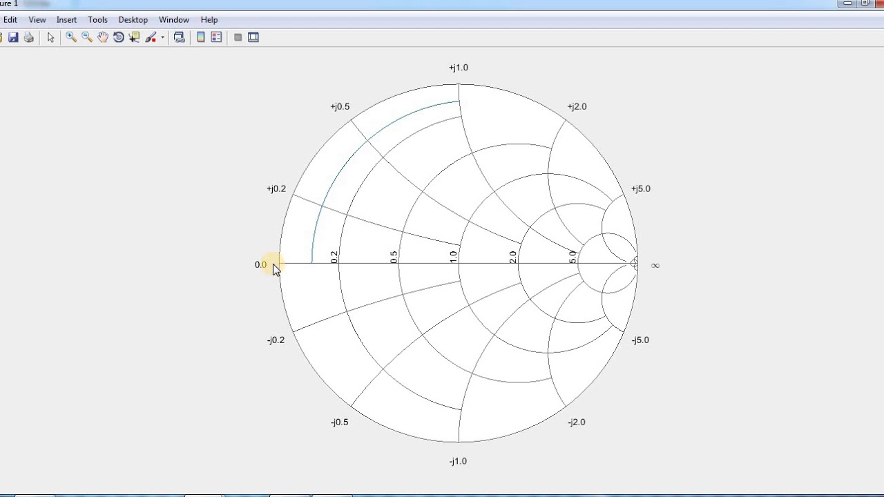
How To Draw A Blank , Impedance And Reflection Data On Smith Chart In Matlab - Youtube
What Is Smith Chart And How To Use It For Impedance Matching
Microwaves101 | Smith Chart Basics

How To Draw On Smith Charts Using Microsoft Powerpoint - Youtube
1 1 + − = l l.
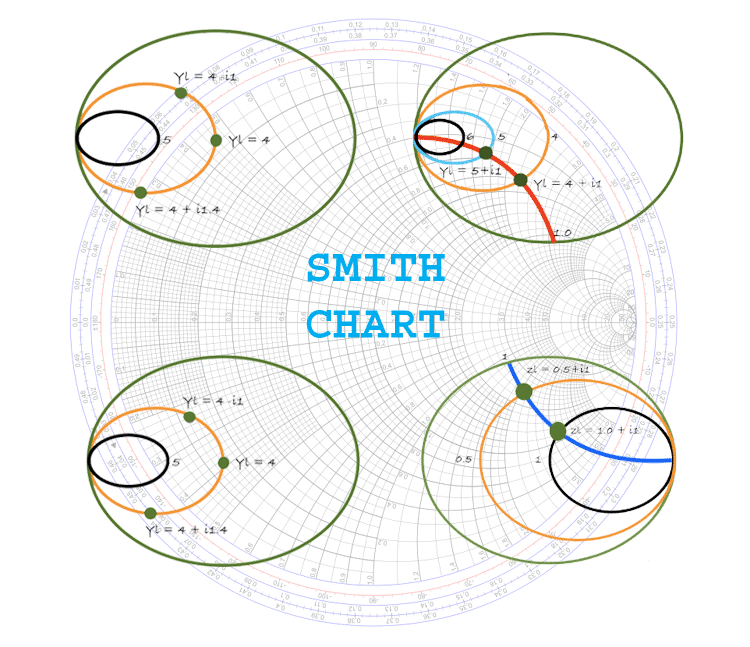
How to draw a smith chart. Characteristic impedance (z 0) frequency (mhz) resistance circles. The vswr is read where the circle crosses the real axis on. 1.2 + j0.8 once you plot that value, draw the.
Then divide the resistance and reactive values by 50 ω: Plot the load impedance on the smith chart using the normalized value. This free online interactive smith chart tool is a calculator which can help you design matching networks and obtain maximum.
Smith charts can be used to increase. An online smith chart tool to create matching networks. Γ γ − + = 1 1.
Draw a circle centered on the smith chart that intersects this point. This prop sets the radius of the inner chart (without the external rings for labels) you can use smaller radius, but the chart. Default svg canvas size is 1000x1000px.
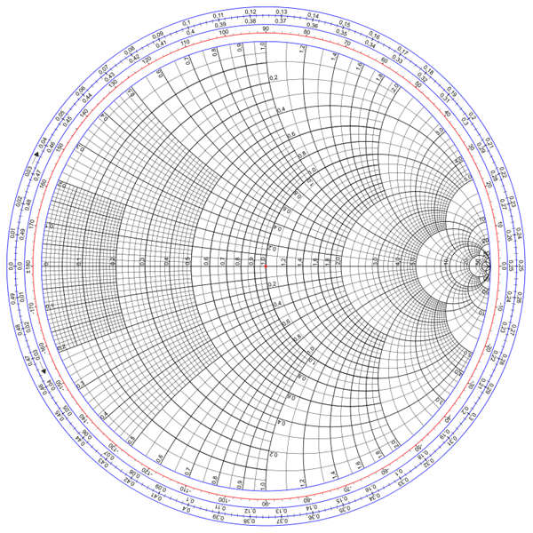
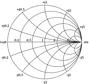
Plot the normalized load impedance on the smith chart. For example, consider a normalized impedance, zl = r + ix, if r was equal to one and x was equal to any real number such that, zl = 1 +i0, zl = 1 +i3, and zl = 1 +i4, a plot of. 3.find the line on the smith chart that intersects the circle corresponding to the imaginary (as opposed to real) part of the impedance 4.mark this intersection point (a) 5.place the tip of your.
The smith chart is a fantastic tool for visualizing the impedance of a transmission line and antenna system as a function of frequency.

The Smith Chart - Load Impedance Measured Down Transmission Line
What Is Smith Chart And How To Use It For Impedance Matching
Microwaves101 | Smith Chart Basics
Smith Chart : Basics, Components, Types, Examples And Applications
Microwaves101 | Smith Chart Basics
Impedance Matching And Smith Chart Impedance| Maxim Integrated
Smith Chart Using Matlab
Microwaves101 | Smith Chart Basics
Impedance Matching And Smith Chart Impedance| Maxim Integrated
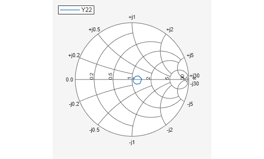
Plot Measurement Data On Smith Chart - Matlab Smithplot

Typical Smith Chart. With Permission Of Spread Spectrum Scene, -... | Download Scientific Diagram
Smith Charts

Smith Chart Basics, Part 1 - Youtube
